Sunday, March 29, 2009

On the storage of Color in meshes

A very short post to clarify a bit the ways in which people can store color (and other) information on a mesh. AFAIK there are mostly three ways to keep color:
  • Per-vertex: each vertex stores a color. A triangular face can have vertexes of different color and inside a triangle the color is linearly interpolated. Color is smooth across the surface.
  • Per face: each face has a distinct color. You can easily see the discontinuity of colors among the faces (no interpolation is usually done.
  • As texture: the most general way that is reasonably decoupled from the mesh itself. You only need a good parametrization.
In MeshLab most of the algorithms (painting, color processing etc.) manage per-vertex color, but a few conversion tools are provided.
  • per-vert -> per -face
  • per-face -> per-vert
  • texture -> per-vert
A per-vert -> texture is strikingly missing :). To be added in the very near future. Obviously assuming the previous existence of a parametrization...
A fourth technique could be mentioned, keeping stuff per wedge, i.e. for each corner of the face we can store different colors (or other attributes), but this approach is rather unused (it can be simulated by duplicating vertices).
Below a few images showing the difference between the three modes on a small (40k tri) mesh; respectively: no color (to give you an idea of mesh density), color by texture, per vertex color, per face color.


Friday, March 27, 2009

Creating Voronoi Sphere


February 2016 update. You can make it online without even installing anything, by using the new browser based version of MeshLab: www.meshlabjs.net 

MeshLab is quite useful for a lot of classical mesh processing tasks, but sometimes it can be used for more weird things. A few weeks ago, after stumbling upon the cool Shapeways 3D printing service I uploaded there a few artsy mathematical sculptures that I created with MeshLab. Here is how I did this one, called Voronoi sphere.
It is a double Voronoi diagram, in the sense that there is a coarse Voronoi diagram over the sphere surface but also the surface that creates the edges of this diagram has been carved to create another finer Voronoi diagram. Such a shape is really very light and thin but much more robust that you could imagine.


  1. Start from a sphere (file->new->Sphere),


  2. Refine it using Filter>Remeshing>Loop Subdivision surfaces. repeat without shame (lowering the edge threshold parameter) until it becomes reasonably well tessellated. 300k faces are enough.


  3. Create some well distributed samples over the surface using
    Filter>Sampling>Poisson Disk Sampling. 50 points are a good choice. Apparently the filters does nothing, but if you reveal the layer panel (guess the icon in the toolbar :)), you can see that there are two layers. Make invisible the first layer and switch the rendering mode to points: you will see the well distributed Poisson samples (hint: alt+mouse wheel change the drawn size of the points).

  4. Create the actual Voronoi diagram by simply choosing the filter
    Color>Voronoi Vertex Coloring. As reported in the top of the parameter window, this filter, given a mesh M and a point-set P, project the points of P over M and color each vertex of M according to the geodesic distance from these projected points. Marking the backdistance flag in the parameter window the filter computes the distance from the borders of the Voronoi diagram instead of the projected sites itself. This filter, beside coloring the mesh, writes on each vertex of the mesh the distance value itself, in the all-purpose attribute named 'quality'.


  5. Make the mesh layer active, and start the Select by vertex Quality filter. enable the preview option and enable visualization of selected faces. Play with the slider until you get something similar to the image on the right; in practice, exploiting the quality value stored onto the vertices that code the distance from the border of the Voronoi diagram we have just selected the faces very near to these borders.


  6. Apply the Filter>Selection>Invert Selection and then delete the selected faces. Edges are probably quite jaggy, so apply a couple of times the simplest of all the smoothing filter, the old classical laplacian filter (Filter>Smoothing>Laplacian Smoothing).

Now stop and save the mesh. Next post will show you how to continue by transforming the current mesh, that is a surface, into a solid object ready to be printed. In the meantime if you like the sculpture, you can buy a small (10 cm) and cheap (less than 20$) copy of this sculpture here.

Wednesday, March 25, 2009

Creating Interactive 3D objects inside a PDF

One of the nice feature of MeshLab is its ability of saving meshes, in a variety of formats. Support for saving meshes in U3D format is useful for creating, using LaTeX, cool appealing PDFs with embedded 3D models.

Yes, that means that when, using a plain Acrobat Reader, you open a pdf like this one, you will be able to freely interact with the 3D model, directly inside the text.

To generate such a pdf you simply need to convert your mesh into u3d format, and include the small snip of latex code generated by MeshLab with the right viewing parameters, in your latex document and simply compile it with pdflatex. Thanks to the Movie15 latex package, you will have your u3D embedded in the pdf. Note that the u3d file format is quite compact; for an example you can look at this pdf that contains the 50k triangle mesh of the Laurana's bust squeezed to less than 250 kb. A zip with sources (latex and u3d file) can be found here.

A couple of notes. The conversion process is done through the use of the Universal 3D Sample Software by directly using the IDTF converter provided with the sample library. The conversion process can take a fairly long processing time (many seconds for a mesh composed by 50k triangles) so be patient! Moreover be careful that the process can fail when involving pathnames with non trivial chars. Moreover very large meshes take a LONG time to be converted, be patient... Acrobat reader support this kind of files since ver. 7.

Monday, March 23, 2009

On the subtle art of mesh cleaning


Most mesh processing algorithms usually require nice two-manifold, watertight, intersection free, well-shaped, clean meshes. Obviously in the real world this does not happen with a great frequency (apart in scientific papers). Common meshes are the most horrible mix of all the possible almost catastrophic degenerate situations.

MeshLab can help the tedious tasks of cleaning meshes in a variety of ways. Let's start with some simple examples involving vertices.
  1. Unreferenced Vertices. Very common issue. Your mesh has some vertices that are not referenced by any triangle. A variety of cause can create these situations (algorithms deleting faces in a non careful way can create them). This situation can be more dangerous than it seems, because they can bring in trash uninitialized data in algorithms that initialize vertex data performing face-based traversal (e.g. normals computations...).
    An easy way to look at the presence of these vertices is simply switching to a point based rendering mode (evenually turning the lighting off, because, by default, unreferenced vertices have null normals). As always happens, sometime this situation is not an error but could be a feature (think to point clouds).
  2. Duplicated vertices. Adjacent triangles does not share the vertices with the same coordinates. Sometimes it is an issue that come directly from some file formats (STL for example store triangles duplicating each vertex). This situation is easy to be detected:
    1. Smooth shading is the same of flat shading: the duplicated vertices do not allow the averagin of normals between adjacent faces that is necessary for smooth shading.
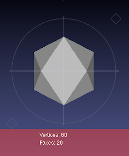
    2. Poor man version of Euler Characteristic does not work: instead of having:
      [face number] ~ 2 * [vertex number]
      you have:
      [face number] ~ 1/3 * [vertex number]
    Again this could be a feature and not an error. Sometimes, duplicating vertices can be used to impose sharp angles when you do not have simple techniques to store multiple normals for the same vertex.
The above cases can be cured, if necessary, by invoking in MeshLab the two filters, Remove Unreferenced Vertices and Remove Duplicated Vertices in the menu named: Filters->Cleaning and Repairing.

First Post

A bit of introduction on the purpose of this blog.
The most common comment that I receive from people that see MeshLab in use is "wow, I did'nt know it could be done..."
The main idea is to report here examples of trivial and less trivial uses of MeshLab in real, on the field (more or less), practical, applications.

A first note. All the posts will refer to stuff done with the latest available betas, e.g. the ones that you can download from the Wiki of MeshLab:
Beta Version of MeshLab